Learning Objectives
By the time you finish this room, you will have learned about the following:
- ISO OSI network model
- IP addresses, subnets, and routing
- TCP, UDP, and port numbers
- How to connect to an open TCP port from the command line
OSI Model
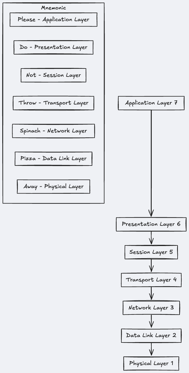
There are Seven Layers on OSI model, u can remember them easily by using mnemonic, “Please Do Not Throw Spinach Pizza Away”.
ERROR
I noticed above image is wrong, mnemonic shud start from bottom
Layer 1 : Physical Layer
The physical layer, also referred to as layer 1, deals with the physical connection between devices; this includes the medium, such as a wire, and the definition of the binary digits 0 and 1. Data transmission can be via an electrical, optical, or wireless signal. Consequently, we need data cables or antennas, depending on our physical medium.
In addition to Ethernet cable, shown in the illustration below, and optical fibre cable, examples of the physical layer medium include the WiFi radio bands, the 2.4 GHz band, the 5 GHz band, and the 6 GHz band.

Layer 2 : Data Link Layer
The Data Link Layer is the second layer (Layer 2) of the OSI model. It is responsible for node-to-node communication and ensures reliable data transfer over a physical link in the network. Here’s a simplified explanation of its key functions:
Key Responsibilities :
-
Framing:
- Converts raw bits into frames (structured chunks of data).
- Adds headers and trailers to help identify where frames start and end.
-
Error Detection and Correction:
- Detects and, in some cases, corrects errors that occur during transmission using mechanisms like checksums or CRC (Cyclic Redundancy Check).
-
Flow Control:
- Prevents a fast sender from overwhelming a slow receiver by managing the rate of data transfer.
-
Media Access Control (MAC):
- Determines how devices share access to the network medium, especially in shared mediums like Ethernet.
- Handles addressing through MAC (Media Access Control) addresses, unique hardware identifiers for devices on the same network.
-
Logical Link Control (LLC):
- Provides logical addressing and helps in identifying the protocol used by the upper layer.
Real-Life Examples :
- Ethernet: A common example of the Data Link Layer in action. It ensures proper data transfer between computers in a local network.
- Wi-Fi: Implements data link layer protocols to enable wireless communication.
Analogy :
Think of the Data Link Layer as the postal worker who ensures that the mail (data) is correctly packaged (framed), addressed (MAC address), and delivered reliably to the right house (device) in a neighborhood (local network).
We expect to see two MAC addresses in each frame in real network communication over Ethernet or WiFi. The packet in the screenshot below shows:
- The destination data-link address (MAC address) highlighted in yellow
- The source data link address (MAC address) is highlighted in blue
- The remaining bits show the data being sent

Layer 3 : Network Layer
 The data link layer focuses on sending data between two nodes on the same network segment. The network layer, i.e., layer 3, is concerned with sending data between different networks. In more technical terms, the network layer handles logical addressing and routing, i.e., finding a path to transfer the network packets between the diverse networks.
- Routes data between different networks, potentially across cities or continents.
- Uses logical addressing (e.g., IP addresses) to identify networks and devices.
- Determines the best path for packets to take when traveling across multiple routers.
- Common protocols: IP, ICMP, and VPN protocols like IPSec or SSL/TLS.
Layer 4 : Transpot Layer
Layer 4, the transport layer, enables end-to-end communication between running applications on different hosts. Your web browser is connected to the TryHackMe web server over the transport layer, which can support various functions like flow control, segmentation, and error correction.
Examples of layer 4 are Transmission Control Protocol (TCP) and User Datagram Protocol (UDP).
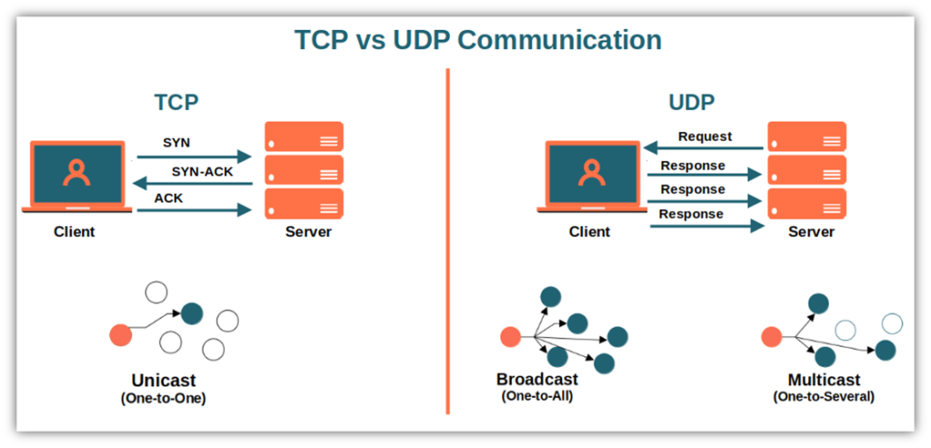
TCP vs UDP
Layer 5 : Session Layer
The session layer is responsible for establishing, maintaining, and synchronising communication between applications running on different hosts. Establishing a session means initiating communication between applications and negotiating the necessary parameters for the session. Data synchronisation ensures that data is transmitted in the correct order and provides mechanisms for recovery in case of transmission failures.
Examples of the session layer are Network File System (NFS) and Remote Procedure Call (RPC).
Layer 6: Presentation Layer
The presentation layer ensures the data is delivered in a form the application layer can understand. Layer 6 handles data encoding, compression, and encryption. An example of encoding is character encoding, such as ASCII or Unicode.
Various standards are used at the presentation layer. Consider the scenario where we want to send an image via email. First, we use JPEG, GIF, and PNG to save our images; furthermore, although hidden from the user by the email client, we use MIME (Multipurpose Internet Mail Extensions) to attach the file to our email. MIME encodes a binary file using 7-bit ASCII characters.
Layer 7: Application Layer
The application layer provides network services directly to end-user applications. Your web browser would use the HTTP protocol to request a file, submit a form, or upload a file.
The application layer is the top layer, and you might have encountered many of its protocols as you use different applications.
Examples of Layer 7 protocols are HTTP, FTP, DNS, POP3, SMTP, and IMAP. Don’t worry if you are not familiar with all of them.
Summary
Reading about the ISO OSI model for the first time can be intimidating; however, it becomes easier as you progress in your study of networking protocols. To help with your studies, we have summarised the ISO OSI layers in the table below.
| Layer Number | Layer Name | Main Function | Example Protocols and Standards |
|---|---|---|---|
| Layer 7 | Application layer | Providing services and interfaces to applications | HTTP, FTP, DNS, POP3, SMTP, IMAP |
| Layer 6 | Presentation layer | Data encoding, encryption, and compression | Unicode, MIME, JPEG, PNG, MPEG |
| Layer 5 | Session layer | Establishing, maintaining, and synchronising sessions | NFS, RPC |
| Layer 4 | Transport layer | End-to-end communication and data segmentation | UDP, TCP |
| Layer 3 | Network layer | Logical addressing and routing between networks | IP, ICMP, IPSec |
| Layer 2 | Data link layer | Reliable data transfer between adjacent nodes | Ethernet (802.3), WiFi (802.11) |
| Layer 1 | Physical layer | Physical data transmission media | Electrical, optical, and wireless signals |
TCP/IP Model Overview
Now that we have covered the conceptual ISO OSI model, it is time to study an implemented model: the TCP/IP model. TCP/IP stands for Transmission Control Protocol/Internet Protocol and was developed in the 1970s by the Department of Defense (DoD). One of the strengths of this model is its ability to allow a network to continue functioning even if parts of it are out of service, such as during a military attack. This resilience is largely due to the design of the routing protocols, which can adapt as the network topology changes.
TCP/IP Model vs. ISO OSI Model
While the ISO OSI model consists of seven layers, the TCP/IP model simplifies this structure. Below is a comparison of the two models, illustrating how the TCP/IP layers correspond to the OSI layers.
Layer Mapping Table
| Layer Number | ISO OSI Model | TCP/IP Model (RFC 1122) | Protocols |
|---|---|---|---|
| 7 | Application Layer | Application Layer | HTTP, HTTPS, FTP, POP3, SMTP, IMAP, Telnet, SSH |
| 6 | Presentation Layer | Grouped into Application | |
| 5 | Session Layer | Grouped into Application | |
| 4 | Transport Layer | Transport Layer | TCP, UDP |
| 3 | Network Layer | Internet Layer | IP, ICMP, IPSec |
| 2 | Data Link Layer | Link Layer | Ethernet 802.3, WiFi 802.11 |
| 1 | Physical Layer | Physical Layer | Ethernet Cables, Fiber Optics, Wireless Signals |
Note: Many modern networking textbooks, such as Computer Networking: A Top-Down Approach (8th Edition) by Kurose and Ross, present the TCP/IP model with five layers by including the Physical layer separately:
- Application
- Transport
- Network
- Link
- Physical
TCP/IP Model Layers
Below is a visualization of the TCP/IP model layers compared to the OSI model using Mermaid diagrams.
Layer Comparison Diagram

TCP/IP Model Layer Diagram

Focus Areas
In the following sections, we will delve deeper into specific protocols within the TCP/IP model:
- Internet Layer: Understanding the IP protocol.
- Transport Layer: Exploring UDP and TCP protocols.
Key Protocols by Layer
Application Layer
- HTTP/HTTPS: HyperText Transfer Protocol (Secure)
- FTP: File Transfer Protocol
- POP3/IMAP: Email retrieval protocols
- SMTP: Simple Mail Transfer Protocol
- Telnet/SSH: Remote login protocols
Transport Layer
- TCP (Transmission Control Protocol): Connection-oriented protocol ensuring reliable data transmission.
- UDP (User Datagram Protocol): Connectionless protocol used for applications requiring speed over reliability.
Internet Layer
- IP (Internet Protocol): Core protocol for addressing and routing packets.
- ICMP (Internet Control Message Protocol): Used for diagnostic and error messages.
- IPSec: Suite for securing IP communications.
Link Layer
- Ethernet 802.3: Wired networking standard.
- WiFi 802.11: Wireless networking standard.
Physical Layer
- Ethernet Cables, Fiber Optics, Wireless Signals: Physical mediums for data transmission.
Questions
- To which layer does HTTP belong in the TCP/IP model?
- Application Layer
- How many layers of the OSI model does the application layer in the TCP/IP model cover?
- 3 (Application, Transport and Data Link)
IP Addresses and Subnets
What is an IP Address?
- A unique identifier for every device (host) on a network, enabling communication. Think of it like a postal address for your computer.
- Uses the TCP/IP protocol suite.
- Primarily uses IPv4 (though IPv6 is increasingly important). When “IP address” is mentioned without specifying a version, it usually refers to IPv4.
IPv4 Addresses:
- Composed of four octets (8 bits each).
- Each octet represents a decimal number between 0 and 255.
- Example: 192.168.0.1 or 172.16.159.243
- Total of 32 bits (4 octets x 8 bits/octet).
Analogy: An IP address is like your home’s postal address; it allows for unique identification and communication (receiving mail/data).
IPv6:
- Also exists, but IPv4 is currently the most common.

At the risk of oversimplifying things, the 0 and 255 are reserved for the network and broadcast addresses, respectively. In other words, 192.168.1.0 is the network address, while 192.168.1.255 is the broadcast address. Sending to the broadcast address targets all the hosts on the network. With simple math, you can conclude that we cannot have more than 4 billion unique IPv4 addresses. If you are curious about the math, it is approximately 232 because we have 32 bits. This number is approximate because we didn’t consider network and broadcast addresses.
Subnets
This explanation describes how IP addresses and subnet masks work together to define a network segment (subnet). Let’s break down the implications:
-
IP Address Structure: An IP address (like 192.168.66.10) is a 32-bit number, often represented in four octets (groups of 8 bits) separated by dots. Each octet ranges from 0 to 255 (256 possible values, as 28 = 256).
-
Subnet Mask (255.255.255.0 or /24): The subnet mask identifies which part of the IP address represents the network address and which part represents the host address within that network. A /24 subnet mask means the first 24 bits of the IP address define the network. In binary, 255.255.255.0 is 11111111.11111111.11111111.00000000. The leading 24 ‘1’s indicate the network portion, while the trailing 8 ‘0’s represent the host portion.
-
Network Address (192.168.66.0): This is the address of the entire subnet. It’s obtained by taking the network portion of any IP address in the subnet and setting the host portion to all zeros. In this example, the network address is 192.168.66.0. This address isn’t typically assigned to a specific device.
-
Usable Host Addresses (192.168.66.1 to 192.168.66.254): These are the IP addresses that can be assigned to individual devices (computers, printers, etc.) within the subnet. There are 254 usable addresses (28 - 2, subtracting the network and broadcast addresses).
-
Broadcast Address (192.168.66.255): This address is used to send a message to all devices on the subnet simultaneously. It’s obtained by setting the host portion of the IP address to all ones.
In short: The /24 notation, along with the IP addresses, clearly defines a network segment that can accommodate up to 254 devices. All devices sharing this /24 subnet will have the same first three octets (192.168.66) in their IP addresses. The last octet distinguishes individual devices within that network. This system ensures that network traffic is efficiently routed to the correct devices within the subnet. The network and broadcast addresses are reserved to manage the subnet.
Private Addresses
Two Types of IP Addresses
There are two main categories of IP addresses:
- Public IP Addresses: Globally unique addresses routable on the internet. These are assigned by internet service providers (ISPs).
- Private IP Addresses: Addresses reserved for internal networks and not directly routable on the internet. They are used to conserve public IP address space and improve network security. Devices using private IP addresses require a gateway (typically a router) with a public IP address to access the internet.
RFC 1918 Private IP Address Ranges
The following ranges are defined in RFC 1918 as private IP addresses: These ranges should be memorized.
- 10.0.0.0/8: 10.0.0.0 to 10.255.255.255
- 172.16.0.0/12: 172.16.0.0 to 172.31.255.255
- 192.168.0.0/16: 192.168.0.0 to 192.168.255.255
Network Address Translation (NAT)
Private IP addresses cannot be directly reached from the internet. To enable devices on a private network to access the internet, a router uses NAT to translate private IP addresses to public IP addresses. The router manages a mapping between the private and public IP addresses, allowing multiple devices on the private network to share a single public IP address. NAT also enhances network security by hiding internal IP addresses from external networks. Further details on how NAT works are deferred to a later section.
Important Note: Attempting to access a device with a private IP address directly from a public IP address will fail unless a specific mechanism such as a VPN or port forwarding is used to establish a connection through the NAT gateway.
Routing : The role of Routers
Analogy
A router is analogous to a post office. Just as a post office sorts and forwards mail to its destination, a router forwards data packets (the “mail”) across a network to their intended recipients.
Router Function
Routers operate at the network layer (Layer 3) of the network model (OSI or TCP/IP). They examine the destination IP address in each data packet and determine the best path to forward the packet closer to its final destination. This path selection involves consulting routing tables, which contain information about network addresses and the optimal routes to reach them.
Multi-Hop Routing
Data packets often traverse multiple routers before arriving at their destination. Each router along the path inspects the destination IP address, consults its routing table, and forwards the packet to the next router on the best path until the final destination is reached. This multi-hop routing is essential for connecting networks across vast geographical distances. For example, a packet travelling between continents would likely pass through many routers along the way.
Key Concepts
- Routing Tables: Databases stored within routers that map network addresses to the best paths (next-hop routers) for forwarding data packets.
- Path Selection: The process of choosing the optimal route for a packet, often based on factors like network distance, bandwidth, and congestion.
- Layer 3 Operation: Routers operate at the network layer, working with IP addresses to make routing decisions.
TCP vs UDP
UDP (User Datagram Protocol)
- Connectionless: UDP does not establish a connection before sending data. Packets are sent independently; there’s no guarantee of delivery or order.
- Unreliable: No built-in mechanisms for error correction or retransmission of lost packets.
- Lightweight: Faster and more efficient than TCP due to its simplicity. Less overhead.
- Suitable for: Applications where speed is prioritized over reliability, such as streaming media (where occasional packet loss is acceptable), online gaming (where small delays are more impactful than lost packets), and DNS lookups.
- Port Numbers: Uses port numbers (1-65535) to identify the sending and receiving processes on different hosts.
TCP (Transmission Control Protocol)
- Connection-oriented: Requires a connection to be established (three-way handshake) before data transmission.
- Reliable: Uses mechanisms to ensure reliable data delivery, including sequencing, acknowledgments (ACKs), and retransmission of lost packets.
- Ordered: Guarantees that data arrives in the order it was sent.
- Heavier: Slower and less efficient than UDP due to the overhead of connection management and error correction.
- Suitable for: Applications requiring reliable data transfer, such as web browsing (HTTP/HTTPS), file transfer (FTP), and email (SMTP).
- Three-Way Handshake: The connection establishment process involves:
- SYN: Client sends a synchronization request.
- SYN-ACK: Server acknowledges the request and sends its own synchronization information.
- ACK: Client acknowledges the server’s response, confirming the connection.
- Port Numbers: Like UDP, uses port numbers to identify processes.
In Summary:
Choose UDP when speed and low overhead are paramount, even at the cost of reliability. Choose TCP when reliable, ordered data delivery is crucial, even if it means slower speeds. The application’s requirements determine which protocol is best suited for the task.
Encapsulation
Encapsulation is the process by which each layer of the network model (OSI or TCP/IP) adds its own header (and sometimes a trailer) to the data received from the layer above. This creates a layered structure where data from the application layer is wrapped successively in headers and trailers by lower layers. Each layer’s header contains information specific to that layer’s function.
- Application Layer: Provides the data (e.g., an HTTP request).
- Transport Layer: Adds a header (TCP or UDP) containing port numbers, sequence numbers (for TCP), and other transport-specific information.
- Network Layer: Adds an IP header containing source and destination IP addresses, routing information, and other network-layer details.
- Data Link Layer: Adds a header and trailer (MAC addresses, error detection) to form a frame suitable for the physical network medium (Ethernet, Wi-Fi).
- Physical Layer: Transmits the physical bits over the network cable or wireless medium.
The process reverses at the receiving end; each layer removes its header/trailer, passing the data up to the next higher layer until the original application data is delivered.
The Life of a Packet
 Based on what we have studied so far, we can explain a simplified version of the packet’s life. Let’s consider the scenario where you search for a room on TryHackMe.
- On the TryHackMe search page, you enter your search query and hit enter.
- Your web browser, using HTTPS, prepares an HTTP request and pushes it to the layer below it, the transport layer.
- The TCP layer needs to establish a connection via a three-way handshake between your browser and the TryHackMe web server. After establishing the TCP connection, it can send the HTTP request containing the search query. Each TCP segment created is sent to the layer below it, the Internet layer.
- The IP layer adds the source IP address, i.e., your computer, and the destination IP address, i.e., the IP address of the TryHackMe web server. For this packet to reach the router, your laptop delivers it to the layer below it, the link layer.
- Depending on the protocol, The link layer adds the proper link layer header and trailer, and the packet is sent to the router.
- The router removes the link layer header and trailer, inspects the IP destination, among other fields, and routes the packet to the proper link. Each router repeats this process until it reaches the router of the target server.
- If you wonder why data link layer header is removed after adding it, check this out : Data Link Layer Header>>>
This simplified explanation omits details like fragmentation, but illustrates the core concept of encapsulation and decapsulation in data transmission over a network. The layers work together, allowing each to handle its specific function without needing knowledge of the details of other layers.
Questions
- On a WiFi, within what will an IP packet be encapsulated?
- Frame
- What do you call the UDP data unit that encapsulates the application data?
- Datagram
- What do you call the data unit that encapsulates the application data sent over TCP?
- Segment
Telnet
The TELNET (Teletype Network) protocol is a network protocol for remote terminal connection. In simpler words, telnet, a TELNET client, allows you to connect to and communicate with a remote system and issue text commands. Although initially it was used for remote administration, we can use telnet to connect to any server listening on a TCP port number.
On the target virtual machine, different services are running. We will experiment with three of them:
- Echo server: This server echoes everything you send it. By default, it listens on port 7.
- Daytime server: This server listens on port 13 by default and replies with the current day and time.
- Web (HTTP) server: This server listens on TCP port 80 by default and serves web pages.
Before continuing, we should mention that the echo and daytime servers are considered security risks and should not be run; however, we started them explicitly to demonstrate communication with the server using telnet. In the terminal below, we connect to the target VM at the echo server’s TCP port number 7. To close the connection, press the CTRL + ] keys simultaneously.
Terminal
user@TryHackMe$ telnet 10.10.148.161 7
telnet 10.10.148.161 7
Trying 10.10.148.161...
Connected to 10.10.148.161.
Escape character is '^]'.
Hi
Hi
How are you?
How are you?
Bye
Bye
^]

telnet> quit
Connection closed.
In the terminal below, we use telnet to connect to the daytime server listening at port 13. We noticed that the connection closes once the current date and time are returned.
Terminal
user@TryHackMe$ telnet 10.10.148.161 13
Trying 10.10.148.161...
Connected to 10.10.148.161.
Escape character is '^]'.
Thu Jun 20 12:36:32 PM UTC 2024
Connection closed by foreign host.
Finally, let’s request a web page using telnet. After connecting to port 80, you need to issue the command GET / HTTP/1.1 and identify the host where anything goes, such as Host: telnet.thm. Next, you need to press Enter twice so your last input line is a blank line. The output below shows the exchange. (The page has been redacted.)
Note: You may have to press Enter after sending the information in case you don’t get a response.
Terminal
user@TryHackMe$ telnet 10.10.148.161 80
Trying 10.10.148.161...
Connected to 10.10.148.161.
Escape character is '^]'.
GET / HTTP/1.1
Host: telnet.thm

HTTP/1.1 200 OK
Content-Type: text/html
[...]

Connection closed by foreign host.
Questions
- Use
telnetto connect to the web server on10.10.148.161. What is the name and version of the HTTP server? - What flag did you get when you viewed the page?
╰─❯ telnet 10.10.148.161 80                                                  ─╯
Trying 10.10.148.161...
Connected to 10.10.148.161.
Escape character is '^]'.
GET / HTTP/1.1
Host: telnet.thm

HTTP/1.1 200 OK
Content-Type: text/html
ETag: "2920831920"
Last-Modified: Thu, 20 Jun 2024 12:39:38 GMT
Content-Length: 20
Accept-Ranges: bytes
Date: Mon, 17 Feb 2025 11:24:52 GMT
Server: lighttpd/1.4.63

THM{TELNET_MASTER}