Background1 Research
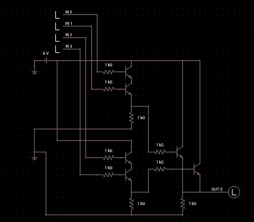
- Chip Description (chip.jpg)
- The chip has four input pins: IN 0, IN 1, IN 2, IN 3.
- It has a power supply of 6V.
- There are five 1 kΩ resistors.
- There is one output pin: OUT 0
- Input Data (input.csv):
- The CSV file contains multiple rows of input values for IN 0, IN 1, IN 2, and IN 3.
- Each row represents a different set of inputs that the chip will process.
Steps to Understand the Chip:
-
Identify the Circuit Configuration:
-
The presence of five 1 kΩ resistors suggests that the chip might be using these resistors in a specific configuration, such as a voltage divider or a logic gate setup.
-
Since there are four inputs and one output, it’s likely that the chip is performing some form of logic operation based on the inputs.
-
-
Analyze the Inputs and Outputs:
-
For each set of inputs in the CSV file, you need to determine what the output (OUT 0) would be based on the chip’s logic.
-
This might involve understanding how the inputs interact with the resistors and the power supply to produce the output.
-
-
Determine the Logic:
-
The chip could be implementing a specific logic gate (e.g., AND, OR, NAND, NOR) or a combination of gates.
-
You might need to simulate or calculate the output based on the input values and the resistor configuration.
-
-
Test with Sample Inputs:
-
Start by testing a few rows from the CSV file to see if you can identify a pattern or logic rule that the chip follows.
-
For example, if the output is high (1) only when all inputs are high, it might be an AND gate.
-
Steps

So This is the circuit image :

as previous we can see there are four inputs and one output and some resistors inside the circuit. lets try to research more about this using deepseek ;)


bro after thinking for 391 seconds : However, without the actual data, it’s hard to say. Given the time invested, I think the intended solution is to use the AND gate outputs. Even though the resulting ASCII seems garbled, the flag might be hidden within it, possibly requiring further decoding like XOR with a key or reversing the bit order.
nvm, back to google.
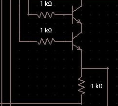
so i googled the this part of the circuit :
 and found that this is and
 AND Gate , resource : https://holst.it/post/logicgates/
AND gate
The AND gate can be constructed Using two NPN transistors:
- A and B are the input signals.
- Q1 and Q2 are NPN transistors.
- R1, R2, and R3 are resistors.
- VCC is the supply voltage.
- Q is the output of the AND gate.

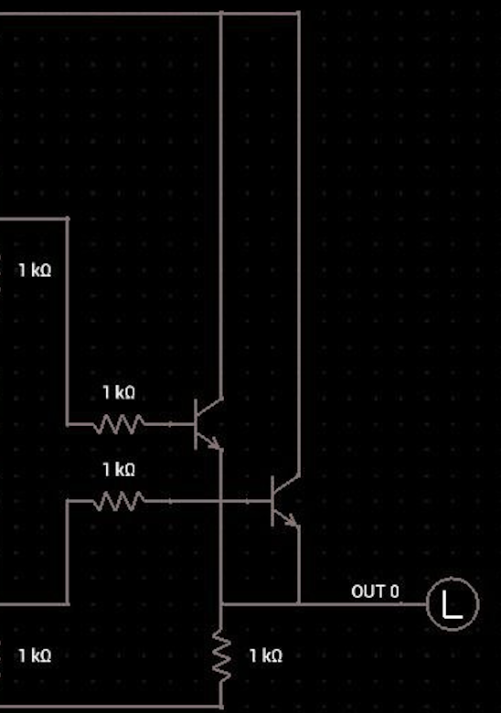
and on the same site i found this :
OR gate
Note, that this gate can be constructed from the NOT and AND gate since ¬(¬A∨¬B)=A∨B.
| A | B | A∧B | ¬A | ¬B | ¬A∨¬B |
|---|---|---|---|---|---|
| 1 | 1 | 1 | 0 | 0 | 0 |
| 1 | 0 | 1 | 0 | 1 | 0 |
| 0 | 1 | 1 | 1 | 0 | 0 |
| 0 | 0 | 0 | 1 | 1 | 1 |
However, it is possible to save a transistor using the following scheme

so its basically this in the circuit :

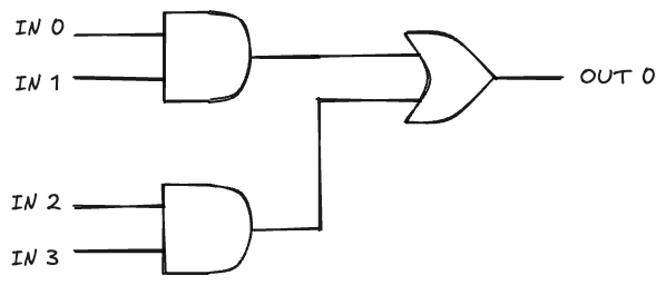
Simplified Circuit
so this is the final simplified circuit

so i guess if we feed the input.csv to this circuit final binary is the flag.

import csv

def and_gate(a, b):
    # AND gate logic: returns 1 if both inputs are 1, else 0
    return 1 if a == 1 and b == 1 else 0

def or_gate(a, b):
    # OR gate logic: returns 1 if at least one input is 1, else 0
    return 1 if a == 1 or b == 1 else 0

def process_row(row):
    # Extract inputs
    in0, in1, in2, in3 = map(int, row)

    # First AND gate (in0 and in1)
    and_output1 = and_gate(in0, in1)

    # Second AND gate (in2 and in3)
    and_output2 = and_gate(in2, in3)

    # OR gate (output of both AND gates)
    or_output = or_gate(and_output1, and_output2)

    return str(or_output)

def main():
    input_file = 'input.csv'
    output_line = []

    with open(input_file, mode='r') as file:
        reader = csv.reader(file)
        next(reader)  # Skip header
        for row in reader:
            output_line.append(process_row(row))

    # Print the output as a single line
    print(''.join(output_line))

if __name__ == "__main__":
    main()
╰─❯ python test.py
010010000101010001000010011110110011010001011111010001110011000000110000011001000101111101000011011011010011000000110101010111110011001101111000001101000110110101110000011011000011001101111101now decrypt it


